Cube7Bonofa

The rules of thumb article below is a part in series of lecturers of Prithvi Datta (UK) ] he used at Colleges of HE

& FE in United Kingdom with practical experimentation for promoting innovation and modification in R&HVAC

Engineering.Thousands of Trainers of Trainees and students of courses from Apprentice Mechanic to Ph.D.

had appreciated the series to master skills for Experimental Studies and Techniques.

Part 1
During my professional duties as Lecturer in R&AC in a Humberside college of HE
&FE we were using R12,22 or 502 for following use of Rule of Thumbs. I tried to
use R410A for the following example using limited data available to me at that
moment.Selected R410 for this application with COP of 8.33 is good example.
why some refrigerant cannot be used without waste of energy and operational and
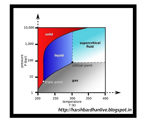
capital losses.Phase & State of Refrigerant at important specific points within as simple.
Refrigeration Cycle working in UK with R410A working at ambient temp. 25 deg
for refrigeration duty of – 20 deg. C.

Refrigeration Cycle should be studied at 12 specific point in the cycle


with R410A working at ambient temp. 25 deg for refrigeration duty of – 20 deg. C
 
Refrigeration Cycle should be studied at 12 specific point in the cycle


Ability to forecast State and Phase of Refrigerant at these 12 points and mastering
P-h Chart using these 12 points can allow true professionals to raise energy efficiency
of Refrigeration Systems and gain best of trouble shooting skills. 

High Side of Cycle                   


Point Position                   State.        State.    Phase of Refrigerant

       
                           (Abs. Bar)  (Deg. C)
1. Inlet of Compressor             3               -18         Superheated Gas
2. Outlet of Compressor    25            80       Superheated Gas

3. Inlet to Condenser              25              70       Superheated Gas

4. 1/8 of Condenser               25               40       Saturated Vapour

5. ½ of Condenser                 25               40       45% Vapour +55% Liquid

6. 7/8 of Condenser               25               40       100% Saturated Liquid

7. Outlet of Condenser             25                 33         Sub-cooled Liquid

8. Inlet of Metering device         25                32         Sub-cooled Liquid 


Low Side of Cycle


9. Outlet of MD                    3                -28       Liquid with Flash Gas


10. inlet of Evaporator        3                 -28       Liquid with Flash Gas

11. ½ of Evaporator            3                 -28       45% Liquid + 55% Vapour

12. Outlet of Evaporator     3                 -22       Superheated Gas
Please visit the site for the next post for the Part-2 of the Rules of Thumbs.

Frazer Goodman has developed the next generation Split Air Conditioner that runs on Solar Power and consumes only 0.34 Watts.

DesktopLightning – Click Here For Free Traffic

Sir James Dyson based in United Kingdom is a Senior Product Designer.He has developed a blade less fan.I wanted to incorporate this technology for our Air-conditioning and Refrigeration products.

Air Multiplier by Sir James Dyson.The experiment itself is so fascinating and opening the vistas for many new potential products to be developed using this technology.

I have been approached by lot of people to teach them system design for the HVAC&R product development and I thought it fit for them to start from basics as without a solid foundation there can be no building.So I thought of compiling the basic formulae first and then go for the system design aspects.It has taken me considerable time to compile these formulae.
I would like to thank Ms. Ashima Saxena for helping me in editing the list of the compilation.

Thermodynamic Design Formulae
Sr.No. EQUATION FORMULAE
1 F = m a Newton’s law of motion
2 P = F / A Pressure
3 ρ = m / V Density
4 W = F d Work
5 PE = m g H Potential energy
6 KE = ½ m V2 Kinetic energy
7 Q = m Cp( t2 – t1 ) Sensible heat
8 Q = m ( h2 – h1 ) Total heat
9 W – Q = dE 1st law of thermodynamics
10 Cpa =1.005 kJ/kgK Heat capacity of dry air
11 Cpw =4.193 kJ/kgK Heat capacity of water
12 Cpv =1.884 kJ/kgK Heat capacity of water vapor
Heat Transfer Formulae
13 Q = – k A dt/dx Conduction
14 Q = hc A ( ts – tf ) Convection
15 Q=σ A Fε FA (t1⁴-t2⁴) Radiation
16 Re = ρ V Dh / µ Reynolds number
17 Pr = µ Cp / k Prandtl number
18 Nu = hc D / k Nusselt number
19 Nu = 0.023 Re0.8 Pr0.4 Dittus-Boelter
Moist Air Phase Formulae
20 P = Pa + Pv Dalton’s Law of partial pressure
21 Pv = R T Perfect gas law
22 Ra = 0.287 kJ/kgK Gas constant of dry air
23 Rv = 0.4615 kJ/kgK Gas constant of water vapor
24 W = 0.622 Pv / (P – Pv) Humidity
25 Pv =P / [1+0.622/W] Vapor pressure from humidity
26 r = (1+W) / v True density of moist air
27 Ps =0.6105 exp [ 17.27 t / (237.3+t) ] Magnus saturation pressure
28 t = 237.3 / [17.27 / Ψ -1]
where Ψ = ln (Ps / 0.6105)
Dew point temperature using the Magnus equation
29 f = Pv/ Ps Relative humidity
30 Pv = Psw-1.8(P-Psw)(db-wb)/(2800-1.3 wb ) Carrier vapor pressure
31 H = 1.005db+W[2500.6+1.85 db-0.023 wb] Enthalpy
32 hfg = 2501.9 – 2.4189 t Latent heat of water vapor
Air Psychometric Formulae
33 ma = ρ Qa Mass flow of dry air
34 Qs = ma Cpm ( t2 – t1 ) Sensible duty
35 Cpm = 1.023 kJ/kgK at typical air-conditioning conditions
36 Qt = ma (h2 – h1 ) Total duty
37 SHR = Qs / Qt Sensible heat ratio
38 b = ( db0 – adp ) / ( dbi – adp ) Bypass factor
39 Qs = h A (db – wb) Sensible heat at wet wick
40 Ql = hd A (Ws,w – W) hfg,w Latent heat at wet wick
41 hd = hc / Cpm Mass transfer coefficient
Room Heat Formulae
42 Q = Uo Ao ( to – ti ) Heat conduction through a wall
43 r = ro+ Σ t/K + ri Wall resistance
44 Qsg = SHGF SC A  CLF Solar heat gain
45 Q = U A CLTD Cooling load temperature difference method
Cold Room Formulae
46 Qpulldown = m C dT Pull down load
47 Qlatent= m ∆W λ Latent load
48 Qrespiration= m R Heat of respiration
Solar Angle Formulae
49 d = 23.45 sin ( 360 (284+n) / 365) Solar Declination
50 LST = CT + (Lstd – Lloc)/15 + E + DT Local Solar Time
51 E = 0.165 sin 2B -0.126 cos B -0.025 sin B Equation of Time
52 B = 360 (n- 81) / 364 Parameter in E
53 h = 15 (LST – 12) Hour angle
54 sin β = cos lcosh  cosd + sin l  sin d Altitude angle
55 cos φ = (cos d sin l  cosh – sin d  cos
l) / cos β
Solar Azimuth
56 cos θ = cos βcos λ  sinΣ + sin β  cos Σ Angle to surface normal
Solar Radiation Formulae
57 IDN =A e -B / sin β Direct Normal Solar Flux
58 IdH = C IDN Diffuse Horizontal Solar Flux
59 ID = IDN cos θ Direct Solar Flux on Surface
Coil Calculation Formulae
60 dQ = hd dA ( ha – hi ) Heat flow on the c oil air side
61 dQ = hr dAi ( ti – tr ) Heat flow on the coil fluid side
62 dQs = hc dA ( ta – ti ) Air sensible heat
63 Q = U A lmtd Duty from UA LMTD method
64 Lmtd = (dti – dto) / Ln( dti / dto ) Log mean temperature difference
65 Q = e Qmax Effectiveness method
66 e = (1 – exp(- Ntu (1- Cr)) / (1 – Cr exp(- Ntu (1-Cr)) Counter-flow effectiveness
67 Cr = Cmin / Cmax Capacity ratio
68 Ntu = U A / Cmin Number of transfer units
Steam Formulae
69 λ = 2164 kJ/kgK Latent heat of vaporization at 2 bar gauge pressure
70 λ = 333.6 kJ/kg Latent heat of freezing
Fluid Flow in Pipes Formulae
71 dPfriction = ½ ρ ƒ L V2/ Dh D’Arcy Weisbach friction equation
72 1/√ƒ = -2 Log [ ε / (3.7 Dh) + 2.51 / (Re √ƒ) ] Colebrook friction factor
73 Dh = 4 A / P Hydraulic diameter
Duct Design Calculation Formulae
74 P + ½ ρ V2 + ρ g H = constant Bernoulli equation
75 P1 + ½ ρ V2 + r g H1 = P1 + ½ ρ V2 + ρ g H1 + Ploss Modified Bernoulli
76 dP = ½ ρ Vd2 [ 0.4 ( 1 – Vd/Vu)2 ] Branch straight through dp
77 Def = 1.3 (ab)0.625 / (a+b)0.25 Effective diameter of rectangular duct
78 dP = ½ ρ V2 [ (A1/A2)2 – 1 ] dP for ideal flow through a nozzle
79 dP = ½ ρ V2 [ 1 – (A1/A2) ]2 dP for sudden enlargement
81 Re ≈ 67 V Dh standard air with V (m/s) and Dh (mm)

Hydrocarbons are refrigerants that can be used as an alternative to fluorocarbon refrigerants in some refrigeration and air conditioning applications.
The term ‘Hydrocarbon’ encompasses following:
A) Ethane (R170)
B) Propane(R290)
C) Butane (R600)
D) Isobutane (R600a)
E) Propylene (R1270)

Properties
1) Hydrocarbons are highly flammable.
2) They have a low toxicity.
3) Hydrocarbon refrigerants are fully compatible with nearly all lubricants commonly used in refrigeration and air conditioning systems. One major exception to this rule is lubricants containing silicone and silicate.

Comparison with HCFC
1) HVAC professionals have made a comparative study on the performance of hydrocarbon refrigerants R290, R600a and R1270 with that of HFC refrigerant R22 and found that in comparison to R22, hydrocarbon refrigerants have similar or better ability.
2) An experiment on a new refrigerant blend comprising R134a (a HFC) and hydrocarbon refrigerants R600a and R290, with a view to finding a replacement for the CFC refrigerant R12 in domestic refrigerators. The experiment concluded that the blend has been identified as a promising alternative to be used as a refrigerant in a conventional R12 system and that the blend reduced energy consumption by 4 to 11%.
3) Hydrocarbon refrigerants generally are compatible with the materials used in systems designed for R22 and often can use the same or similar lubricants, however, their substitution requires significant attention to safety issues including application specific considerations.
4) It has been observed that no (one) refrigerant has been identified as a suitable alternative for most applications,though they identify that some refrigerant blends “offer good options”. Blends can be HFC/HFC or HFC/HC.
5) Hydrocarbons may be suitable in some applications, and may not be in others, so every application needs to be carefully assessed on its merits.

Safety Issues
1) As mentioned above, hydrocarbon refrigerants are flammable and therefore certain restrictions are placed on their use to ensure safety.
2) All electrical contacts must be sealed or non-sparking.
3) The refrigerant charge in a system below ground level must not exceed 1.0 kg.
4) Sealed systems not exceeding 0.25 kg can be cited in any location.
5) Systems with charges exceeding 0.25 kg must not be located anywhere where a sudden loss of refrigerant will raise the concentration in the room or occupied compartment above the practical limit (0.008 kg/m³)
6) Piping for systems exceeding 1.5 kg must be restricted to the room containing the refrigerant.

Hospitals, prisons,
theaters, supermarkets,
schools, hotels,
restaurants, dwellings
Refrigerant charge must not
exceed 1.5 kg per sealed system
• Refrigerant charge must not
exceed 5.0 kg in special machinery rooms for indirect systems
Offices, small shops,

small restaurants,

places for general
manufacturing and
where people work

• Refrigerant charge must not
exceed 2.5 kg per sealed system
• Refrigerant charge must not exceed 10.0 kg in special machinery rooms for indirect systems
Industrial, cold stores,
dairies, abattoir,
non public areas
of supermarkets
• Refrigerant charge must not exceed 10.0 kg in humanly occupied spaces
• Refrigerant charge must not
exceed 25.0 kg for systems
with high pressure side
in special machinery rooms
• No restrictions are placed on the charge size if all parts of the system containing refrigerant are in a special machinery room or in open air

Corporate Acceptance
1) In Europe, many models of domestic refrigerators are charged with hydrocarbon refrigerant in the factory. It is estimated that there are at least 100,000,000 household refrigerators in use around the world containing hydrocarbon refrigerants.
2) Hydrocarbons have also been used in small air conditioning systems and cold drinking water dispensers.
3) Hydrocarbon refrigerants are also commonly used in large process refrigeration systems in the oil and gas industries.

The use of Carbon dioxide as a refrigerant declined for a number of reasons, including changes in technology and the introduction of fluorocarbon refrigerants, which were seen as ‘safety refrigerants’.

Properties

A) Carbon dioxide has an ozone depletion potential (OPD) of zero and a global warming potential (GWP) of 1.
B) It is generally regarded as a cheap and easily available  refrigerant, and many regard it as an ideal refrigerant.
C) Carbon dioxide is non-toxic. It has low toxicity and is non-flammable.
D) Carbon dioxide is colorless, odorless and is also heavier than air.If enough carbon dioxide builds up in an enclosed space it will begin to displace oxygen and can cause asphyxiation in anyone present within the space. As carbon dioxide is colorless and odorless,a  person in the space will not be able to tell unless proper detectors and alarms are installed.
E) As a refrigerant, carbon dioxide operates at a higher pressure than fluorocarbon and other refrigerants. While this presents design challenges it can usually be overcome in systems designed specifically in suction and discharge tubing.
F) Carbon dioxide is not compatible with commonly used refrigeration system lubricants.It is not suited for use with polyols ester (POE) and poly vinyl ether (PVE) lubricants, and it has only limited applications with poly alkylene glycol (PAG) lubricants.

Safety Issues

A) Some restrictions are placed on the size of the refrigerant charge, with additional allowances made for systems with detectors and alarms fitted, and as carbon dioxide is heavier than air the standard requires “suitable precautions” to be taken to prevent the undue accumulation of refrigerant in occupied spaces in the event of a leak.
B) As with fluorocarbon refrigerants, the standard also requires the system to be designed to withstand the refrigerant’s maximum operating pressure.
C) The International Institute of Refrigeration (IIR) identified carbon dioxide’s high working pressure as the main drawback to its use.

PT Chart CO2

Thermodynamic Properties

1) Carbon dioxide is colorless. At low concentrations, the gas is odorless. At higher concentrations it has a sharp, acidic odor.
2) At standard temperature and pressure, the density of carbon dioxide is around 1.98 kg/m3, about 1.5 times that of air.
3) Carbon dioxide has no liquid state at pressures below 5.1 standard atmospheres (520 kPa). At 1 atmosphere the gas deposits directly to a solid at temperatures below −78.5 °C and the solid sublimes directly to a gas above −78.5 °C. In its solid state, carbon dioxide  commonly called dry ice.
4) Liquid carbon dioxide forms only at pressures above 5.1 atm; the triple point of carbon dioxide is about 518 kPa at −56.6 °C.The critical point   is 7.38 MPa at 31.1 °C.

Corporate Acceptance

Coca Cola company stated that the company’s preliminary field tests proved the technology to be reliable, in real life circumstances the equipment often used less energy than equivalent equipment using HFC as a refrigerant.
Till 2006, the company was market testing a range of drinks fridges and vending machines using carbon dioxide refrigerants.


Most of the refrigeration and air conditioning equipments in the world today uses fluorocarbon refrigerants to facilitate the heat transfer process.Fluorocarbon refrigerants are synthetic chemicals which causes a high global warming potential,and are a greater threat to the ozone layer as well if released to the atmosphere.There are alternatives to these HFC’s that can help to mitigate some of the environmental risks.These are called ‘natural’ refrigerants because the substances also occur in nature, these alternatives are:
1) Ammonia, 2) Carbon Di Oxide, 3) Hydrocarbons

Ammonia PT Chart

Ammonia (R717)
Ammonia is a naturally occurring substance that can be used as a substitute to fluorocarbon refrigerants in refrigeration systems.

Properties
A) Ammonia (NH3)- R717 is a colorless gas with high pungent smell at atmospheric pressure, and possesses the ideal environmental properties for a refrigerant – it has both a zero ozone depletion potential (ODP) and a zero global warming potential (GWP).
B) These properties make ammonia an attractive prospect as a refrigerant, given that fluorocarbon (HFC) refrigerants can have global warming potentials as high as 3900.
C) Many people are familiar with ammonia as an ingredient in fertilizers and other products. Ammonia carries a B2 safety classification,meaning that it has a high toxicity, and also carries a medium flammability risk.
D) Ammonia is not compatible with commonly used refrigeration system lubricants.It is not suited for use with polyol ester (POE) and poly vinyl ether (PVE) lubricants and it has only limited applications with poly alkylene glycol (PAG) lubricants.

Safety Issues
A) A glass of drinking water can contain as much as 1 mg of ammonia,a 200gms steak as much as 13mg, and some food additives can contain as much as 18 mg.cigarette smoke and even the air we breathe also contains ammonia in small amounts.
B) This demonstrates that the human body can deal with ammonia in small quantities.
Generally, any amount in the atmosphere below 20 parts per million (ppm) is regarded as not dangerous. At amounts of up to 53 ppm, ammonia’s characteristic odor will be noticeable.
C) In amounts of 300-400ppm, prolonged exposure will become unpleasant, and in amounts over 700 ppm it can cause burns and serious
damage to eyes. In amounts of 5000 ppm or above, exposure can be lethal to humans within five minutes.

Thermodynamic Properties
A) Vapor mass is lighter than air ( 0.6 compared to air 1.0).
B) Ignition will occur at 651 C when vapor concentration is between 15% and 28%.
C) Ammonia corrodes galvanized metals, cast iron, copper, brass & copper alloys.
D) It weighs 5.15 pounds(2.34Kgs) per gallon(3.78 Liter) in liquid conditions (water weight 8.33 pounds per gallon).
E) Boiling point of liquid ammonia at atmospheric pressure is -2.22 C.
F) Liquid ammonia expands 850 times its liquid volume at atmospheric pressure.

Green HVAC Natural Refrigerants Natural HVAC


EPS often called as Thermocol.It is designed keeping in mind the excellent thermal insulation and low cost.When assembled inside the window air conditioner it gives an excellent mechanical fastening to the partition plate and evaporator.Usually,the density of the designed components is kept at 30 kg/cu.m and the granular size is 5 mm.
Small Air Conditioner Mfg.Room Air Conditioner-Drain TrayHVAC Design-Blower Housing
HVAC is in great demand in America & Europe it is one of the fastest growing consumer durable segment in India…!! The below pics were taken when we were having share holders meet in Lloyd and I was assigned the task of  making Product  Display Area for R&D.
Floor & Cassette Air Conditioner
H VAC-My Passion
R&D Display